Astronomical Equipment
| Sentinel of the Caprock Observatory Astronomical Equipment |
The astronomical equipment used in the Sentinel of the Caprock Observatory (SOCO) has evolved over the past few years. The main shift has been from equipment that is suited primarily for amatuer observing to more research-grade equipment. A number of the components have been acquired not only to support current needs but also in anticipation of future upgrades to the system. The following sections describe the main components of the SOCO astronomical imaging system. The main telescope currently used at SOCO is an Orion 120mm (4.7-inch) EON Apochromatic Refractor originally purchased in 2011. The scope has a normal focal length of 900 mm, giving it a 7.5 F-ratio. The optical design is an air-spaced doublet with the rear element made from FPL-53 ED glass. The optical tube is made from a seamless aluminum tube with an overal length of approximately a meter (with dew shield extended). The scope weighs approximately 21 pounds. The scope was manufacturered in China, with the workmanship, assembly and finish excellent. An early view of the scope, mounted on its tripod, is shown in Figure 1. At the time of its purchase, the 120-mm was the largest refractor available in the Orion EON line. For a modestly priced telescope, its optical performance is very good. Views produced with the scope are sharp with high contrast and no appreciable color distortion. There is a small difference among the optimum focus points for the red, green and blue spectral bands. The red focus is 0.0044 inch (0.112 mm) shorter than the green focus, while the blue focus is 0.0053 inch (0.135 mm) longer than the green focus. When optimally focused, images of stars do not exhibit appreciable bloating in the blue spectral band. The scope has a theoretical resolution of around 1 arc-second over the visible wavelengths, but this is practically limited by atmospheric effects. All in all, this is a pretty good scope for imaging astronomical objects with sizes of around 5 arc-minutes or greater. As shown in Figure 1, the Orion 120mm EON Apochromatic Refractor originally came with an Orion Sirius EQ-G German Equatorial mount. Removed from the tripod, this mount was installed on the pier in SOCO using a custom-built adapter, as shown in Figure 2. The ASCOM interface for this mount is very good, allowing it to be operated through Cartes du Ciel running on a laptop. In addition to the go-to capability in Cartes du Ciel, the mount could be manually operated using a standard PS3 game controller (which was more convenient than the hand-held controller provided with the mount). The EQMOD Project provides a suite of open-source applications for use with this mount. There is also a large and active YAHOO! online community for this mount, which is a great reference source. Unfortunately, a major problem developed with using the Sirius EQ-G mount in SOCO. The mount is normally capable of handling a load of around 25 pounds. This is adequate for normal visual viewing or imaging using a digital SLR camera. However, with the addition of a heavy (around 6 pounds) imaging camera, autoguiding scope and camera, and motorized focuser to the scope, the payload weight began to exceed the capabilities of the mount. In ascending mode, the mount had a hard time responding to the commands from the autoguider, resulting in the target drifting out of the cross-hairs in the autoguider software. As you might expect, this was very bad for imaging. The problem persisted even after changing the balance of the scope. This was not really a flaw with the mount— it's just that I was hanging too much stuff on the scope for it to handle. In March of 2013 it was decided to go to a more robust telescope mount. In making the switch, the future plans for SOCO involving the possible acquisition of a larger telescope were considered (see the last section on this page). So, if and when a larger scope was acquired, the mount for it would already be there. After considerable investigation and comparison of brands and models, it was decided to go with the Astro-Physics Model 1600GTO German Equatorial mount. This is a massive mount with a load capability of around 220 pounds, adequate for any of the future scopes considered for SOCO. This was a major purchase, costing about the same as my last new car. However, this should be the last telescope mount I'll need to buy. After fabricating an adapter plate, the new mount was attached to the pier in SOCO (Figure 3). To accomodate the increased height of the new mount, about one foot was cut off the top of the wooden pier. The Orion 120mm EON Apochromatic Refractor was attached to the new mount using a 16" Easy-Balance Dovetail Saddle Plate and a 12" Vixen Dovetail Converter, both available from Astro-Phyisics (Figure 4). One additional piece of mounting hardware was included in the setup. For proper pointing, it is important that the alignment of the scope should match the alignment of the mount, i.e., they should both point in exactly the same direction. To achieve this, an ADM Accessories MAX-HD Altitude/Azimuth Aiming Device (Figure 5) was included between the scope and the mount. This device allows precise adjustments in the vertical and lateral pointing of whatever is attached to it (in this case, the SOCO telescope). The Astro-Physics Model 1600GTO German Equatorial mount performs extremely well. It has solved the problem encountered with the previous mount. In fact, the mount probably hardly notices the presence of the telescope and other equipment mounted to it when it moves (a payload of 30-40 pounds is nothing to this mount). I was immediately impressed with how rapidly the mount moves in slewing to a position. An example of its movement is given in Figure 6. Figure 6. Click on the play button above to see a movie showing how the Astro-Physics mount moves (older browsers might not support this function). I've found that, with proper alignment and calibration of the telescope mount, I can obtain acceptable unguided images with a duration of around 2 minutes. Longer exposures require guiding. At SOCO, I use off-axis guiding involving a second, smaller telescope attached to the main telescope (see Figures 1, 2 and 4). The autoguiding scope is an 80-mm f/5 Orion ShortTube 80 with a 400-mm focal length. This is a cheaper (and presumably lower-performing) version of the 80-mm telescope available in the Orion EON line, but it is completely adequate for the task of autoguiding. Orion suggests mounting it to the main scope using finder scope mounting rings that allow adjustment of the pointing of the scope. I don't like that arrangement because it is susceptible to flexure. Instead, the 80-mm guide scope is attached to the main scope using the hinged tube rings that clamp onto the telescope tube to hold it firmly to the main scope. As shown in Figure 7, this provides a solid attacment of the guide scope to the main scope that minimizes the chances of flexure. The guiding camera is an Orion StarShoot Autoguiding camera. This is a relatively inexpensive camera, but seems to work well for autoguiding. It captures a 1280 X 1024 8-bit monochrome image at a refresh rate as fast as 0.5 second. It is connected directly to the RJ-12 autoguiding connector on the Astro-Physics mount. A second connection (and source of power) goes to a laptop containing the control software. I use the PhD Guiding Software that came with the camera. This software also works with other guiding cameras, and can be downloaded from the StarShoot Support Webpage. The accuracy of the guiding is quite good— typically sub-pixel for the StarShoot camera. As shown in Figure 7, an additional device that I use in the autoguiding setup is an Orion X-Y Guide Star Finder. This device fits between the guiding scope and the autoguiding camera and allows the camera to be racked in the X- and Y-directions relative to the centerline of the guiding scope. This greatly increases the virtual FOV of the camera, as the area of the CCD chip in the camera is apparently much smaller than the view provided by the scope. Using it, I haven't had a situation where I couldn't find a satisfactory guiding star. This is a neat device but, unfortunately, the last time I checked the Orion website, they were no longer selling it. The EON 120mm Apochromatic Refractor originally came with a manual dual-speed Crayford focuser (see Figure 1). In April of 2014, this was upgraded to a motorized focuser by adding a Seletek "Tarsier" motorized focusing system available from Lunatico Astronomia (Figure 8). The Tarsier system worked reasonably well but, in conjunction with the existing focuser, ran into some problems. First, the Tarsier provides relative, not absolute, focusing. In other words, you cannot go back to the exact same focus point. This is particularly true if you change the direction (inward versus outward) of focusing. Second, the Tarsier could not always hold the focus point, particularly when the scope was pointed at a high elevation angle. This was more a problem with the Crayford focuser itself because, over time, it had lost its capability to support heavy payloads like the SOCO imaging camera. This probably would not have been a problem with a lighter payload. As a result, in October of 2014 the existing Crayford focuser was completely replaced with a substantially more robust focusing system. Chosen as the replacement was an Optec Model TCF-S3i Integrated Temperature Compensating Focuser. This is a heavy-duty 3-inch focuser with a payload capacity of 25 pounds, capable of handling any digital camera on the market. The two focusers are compared in Figure 9. The TCF-S3i was chosen in part with an eye on the future. Many larger telescopes require 3-inch focusers (as opposed to the 2-inch focuser previously on the SOCO scope), so acquiring one now would preclude having to buy another focuser in the future. The TCF-S3i is an absolute focuser. It has a focus travel of 1 inch, and this range is broken down into 10,000 steps. Returning to the same focus point is repeatable regardless of the direction (inward or outward) of focus. With each focus step representing 0.0001 inch, extremely fine focusing can be achieved. The -i version of this focuser is controlled from a laptop using software provided by Optec. The focuser uses temperature compensation based on measurements made with a thermistor attached to the telescope tube. Once optimum focus has been achieved, the focuser will automatically correct for changes in scope temperature over the duration of the imaging session. The focuser-camera train is shown in Figure 10. Machinists at Optec fabricated a custom adapter to mate the focuser to the back of the telescope tube. Several elements are placed between the focuser and camera to assist in the transition between the two. To accomodate instances when additional back focus is needed between the focuser and camera, an extension tube capable of adding 2.2 inches of back focus (in 0.3-inch increments) has been placed immediately behind the focuser. Following the extension tube, a stepdown adapter reduces the diameter of the optical train from 3" to 2" to accomodate the aperture of the QSI camera. The TCF-S3i Integrated Temperature Compensating Focuser was a substantial purchase. However, its performance has been truly exceptional. Not only has it eliminated the previously encountered focusing problems, but it has also greatly simplified the focusing procedure (essentially just "dialing in" a number on the computer), making imaging a much more efficient and enjoyable operation. Prior to SOCO, I experimented with astro-imaging using a digital SLR. However, I quickly realized that imaging many deep-space objects required the capabilities of cooled digital cameras designed specifically for this task. After considerable investigation and comparison of brands and models, I decided to go with the QSI Model 583 Monochrome camera primarily becaise it represented a relatively small, fully integrated (the filter wheel is part of the camera) system with a moderate price. The QSI 583 as received from the dealer is shown in Figure 11 (note that QSI does not offer this model any more but has replaced it with newer models). The QSI Model 583 Monochrome camera has a number of attractive features. Its CCD chip (a KAF-8300) has microlenses that increases its overall quantum efficiency. It is also non-blooming, so I don't have to worry about removing blooming artifacts from long-exposure images. While the overall dimensions of the CCD are modest (17.96 X 13.53 mm), its pixels are small (5.4 microns) so that it has a relatively large array size (3326 X 2504 pixels). A nice feature is that the filter wheel is integrated into the camera body and thereby minimizes the thickness of the camera/filter wheel combination. As originally purchased, the filter wheel could hold five standard 1.25" filters. Initially, I installed Astrodon Series E red, green, blue, and luminance filters in the wheel (Figure 12). In early 2015, I decided to upgrade the QSI camera to incorporate an 8-position filter wheel. This would allow the use of narrow-band filters (Hα, Hβ, and OIII) along with the broad-band filters in the camera. This modification involved changing the front cover of the camera to a larger version that could hold the 8-position wheel. The upgraded version is shown in Figure 13. At the time of this upgrade, I also replaced the Astrodon filters with Baader filters. The current version of the camera is shown in Figure 10 and Figure 14. In this figure, notice the red lanyard attaching the camera to the upper part of the telescope mount. Twice I had the camera fall out of the previous Crayford focuser, landing with a thud on the observatory floor. After much cursing, I determined that in each case the camera has survived with no damage, probably because the subfloor beneath the regular floor in the observatory provided a bit of cushion to the impact (also probably because the QSI camera is really well-constructed). Now I use the nylon lanyard to catch the camera in case of another fall. In operation, the various components of the SOCO imaging system are run by computers. The control of the SOCO imaging system is shown diagrammatically in Figure 15. In this system, three laptop computers control the autoguider, the main imaging camera, and the temperature-compensated focuser. Each laptop runs the software for its respective device— PhD for the autoguider, Maxim DL for the imaging camera, and Optec TCF focusing application for the focuser. In reality, all these programs could be run simultaneously on one laptop. So, why use three laptops? Well, in part because I had a couple of older laptops laying around unused. But, more importantly, using a separate laptop for each program means that the programs don't have to compete for CPU and data bus time. Thus, each program can run at its maximum speed. It also eliminates possible conflicts for USB ports. There is a fourth computer— the one inside the Astro-Physics mount. This is operated separately using a hand-held keypad controller. The mount can be run from a laptop, using planetarium software such as Catres du Ciel. In fact, this is the way I used to control the old Sirius EQ-G mount. But, I find that the use of the hand-held controller is a bit simpler and easier than using a separate laptop. Since the Astro-Physics is a GOTO mount, it already contains the coordinates of most deep-sky objects that I'm likely to image. For objects not in its lists, I can directly input the object's RA and Declination using the keypad controller. While the diagram in Figure 15 suggests a spiderweb of cables runs around the imaging system components, in reality all the cables from the autoguider, main camera and focuser physically run through the Astro-Physics mount. Thus, they are out of the way and not available to get snagged as the mount moves the scope. There are only three cables running from the mount, one to each laptop. I keep these on one side of the observatory, and don't walk through the area they're in. Figure 16 shows an image inside SOCO with the three laptops running (normally the displays of the laptops are tilted down to reduce the amount of scattered light inside the observatory). When used alone, the QSI camera sits at the prime focus of the telescope (i.e., there are no other optical elements in the optical path after the primary lens). Thus, the imaging system has a nominal focal length of 900 mm. For the size of the CCD chip in the QSI (17.96 X 13.53 mm), this produces images that cover a rectangular area of the sky with dimensions of 1.143 X 0.861 degrees. Some larger astronomical objects, like the open cluster M 7 in Scorpius, may not completely fit within this field of view (FOV). On the other hand, smaller objects (like M 104, the Sombrero Galaxy) will occupy only a small portion of the FOV without exhibiting much detail. To get around these problems, auxilliary optics can be placed in the focal path to decrease or increase the size of the object within the imaging FOV. At SOCO, this is achieved using two auxilliary optical devices (Figure 17). To reduce the size of the object in the FOV (by decreasing the apparent focal length of the optical system), the Optec NextGen Ultra Widefield 0.7X focal reducer is attached to the front of the camera. To increase the size of the object in the FOV (by increasing the apparent focal length of the optical system), the TeleVue 2X PowerMate is attached to the front of the camera. Characteristics of the three optical systems used at SOCO are summarized in Table 1. In this table, FOVl is the length (in degrees) of the rectangular area of the sky representing the imaging FOV, while FOVw is the width (in degrees) of the rectangular area of the sky representing the imaging FOV.
Main Telescope
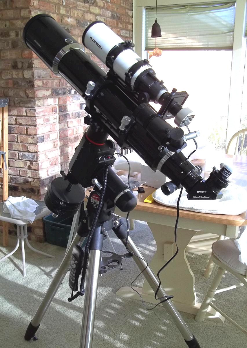
Figure 1. The EON 120mm Apochromatic Refractor as originally purchased from Orion (also shown is the 80-mm autoguiding scope).
Telescope Mount
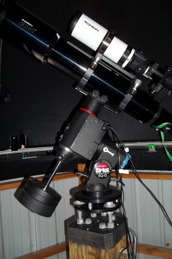
Figure 2. The original Orion Sirius EQ-G mount installed on the pier in SOCO.
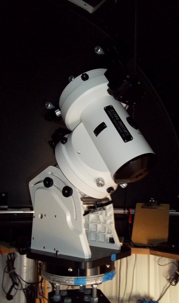
Figure 3. The Astro-Physics Model 1600GTO German Equatorial mount installed on the pier in SOCO.
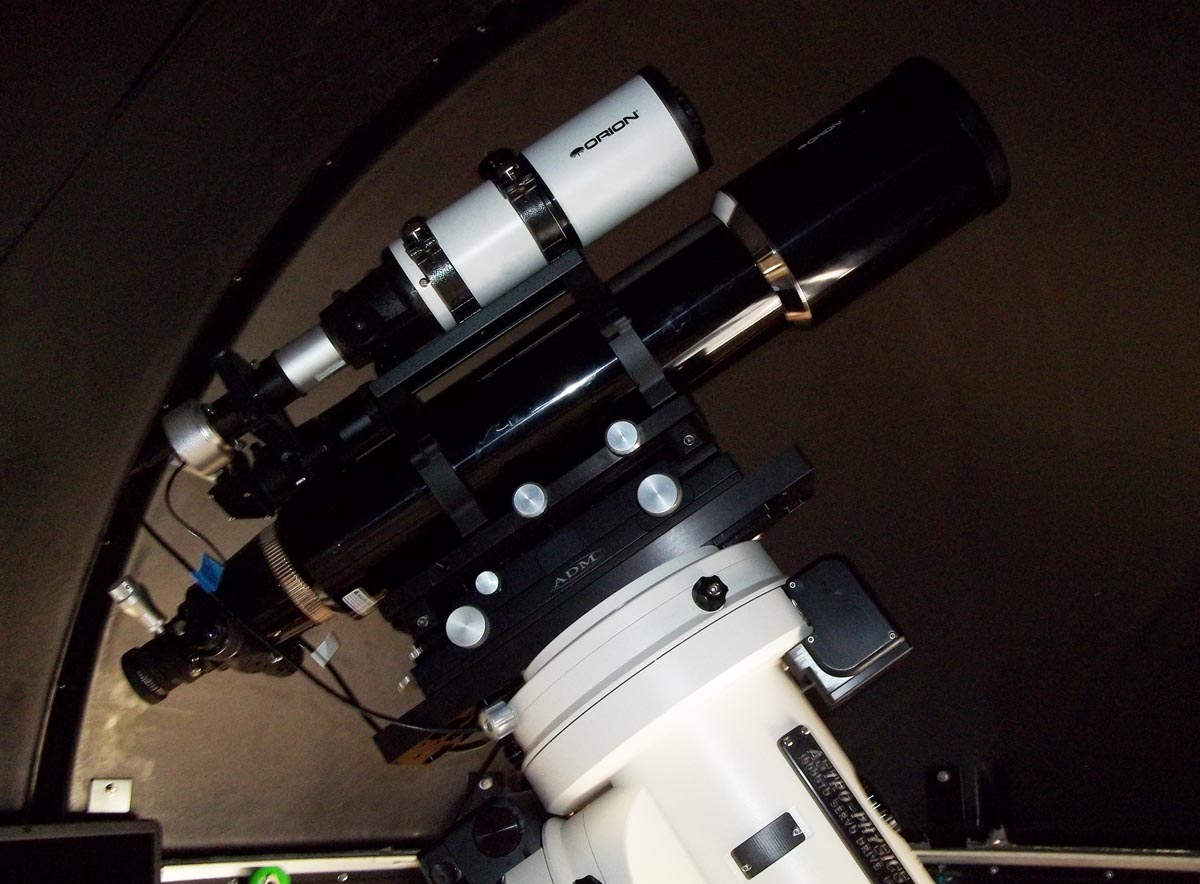
Figure 4. The Orion 120mm EON Apochromatic Refractor attached to the Astro-Physics mount.
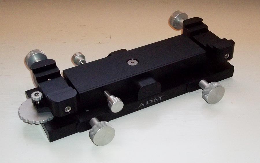
Figure 5. The ADM Accessories MAX-HD Altitude/Azimuth Aiming Device.
Autoguider
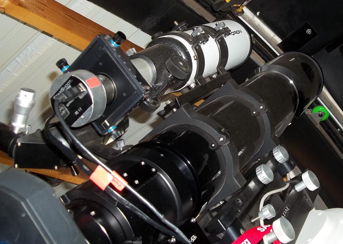
Figure 7. The 80-mm guiding scope, Starshoot autoguiding camera, and Orion X-Y Guide Star Finder attached to the main SOCO scope.
Focuser
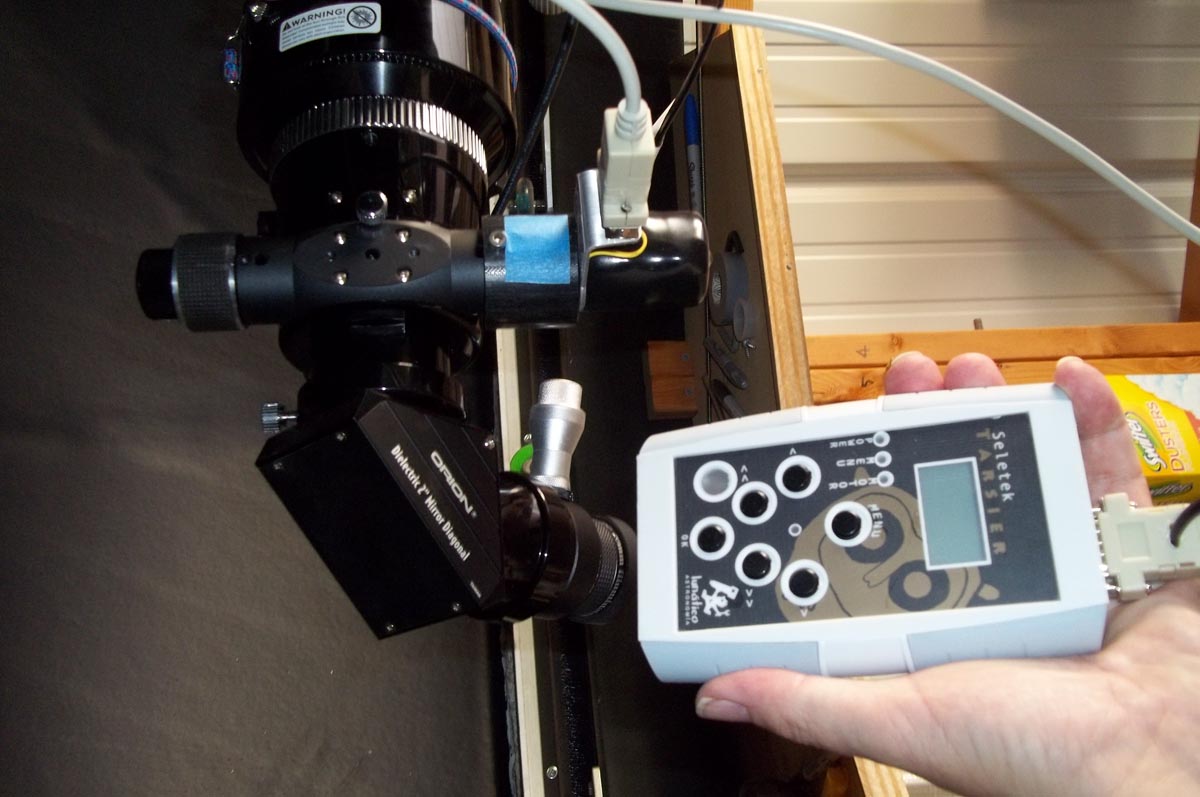
Figure 8. The "Tarsier" motorized focusing system attached to the Crayford focuser on the SOCO main scope.
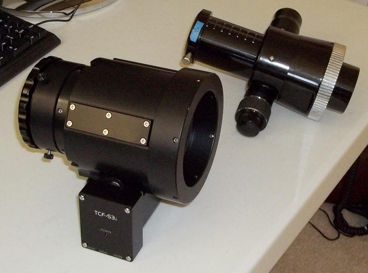
Figure 9. Side-by-side comparison of the old Crayford focuser with the new Optec TCF-S3i focuser.
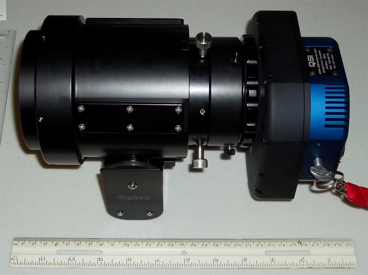
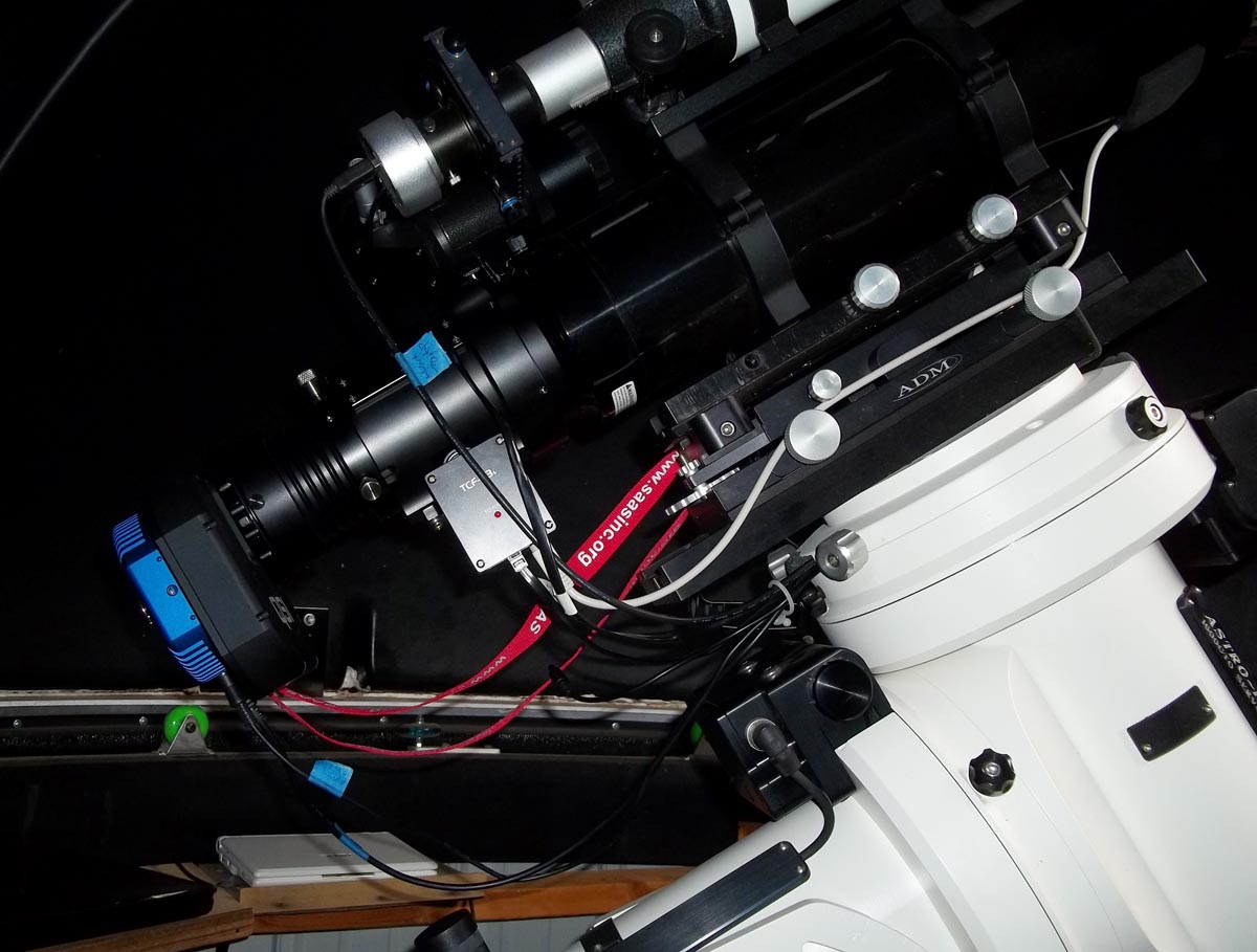
Figure 10. TCF-S3i focuser with QSI camera, telescope adapter, 3" extension tube, and 3" to 2" stepdown adapter.
Imaging Camera
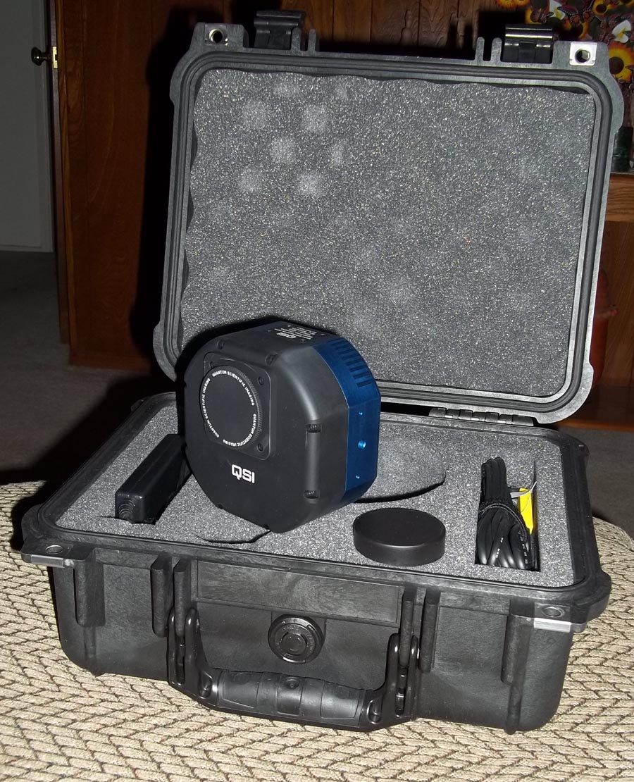
Figure 11. The QSI Model 583 Monochrome camera.
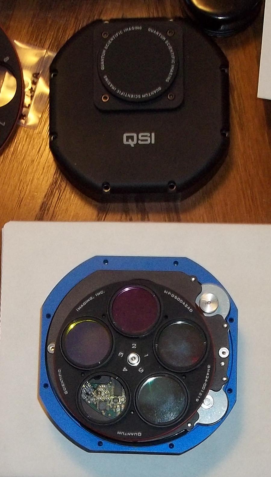
Figure 12. QSI Model 583 Monochrome camera with 5-position filter wheel.
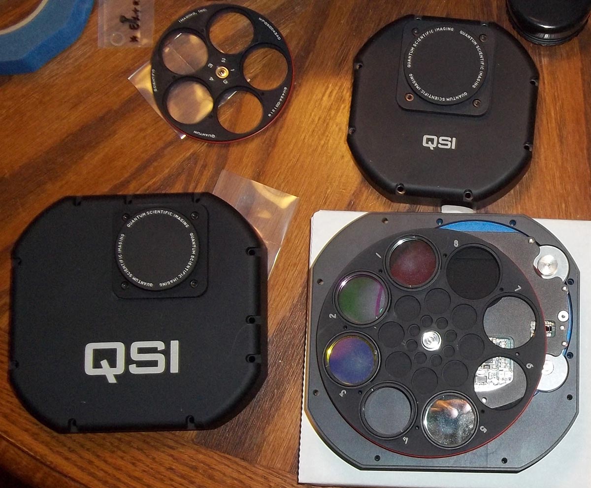
Figure 13. The modified QSI camera with 8-position filter wheel. For comparison, the camera cover and filter wheel of the original camera are also shown to demonstrate the change in size of the system.
Figure 14. The upgraded QSI camera attached to the Optec focuser.
Imaging System Control
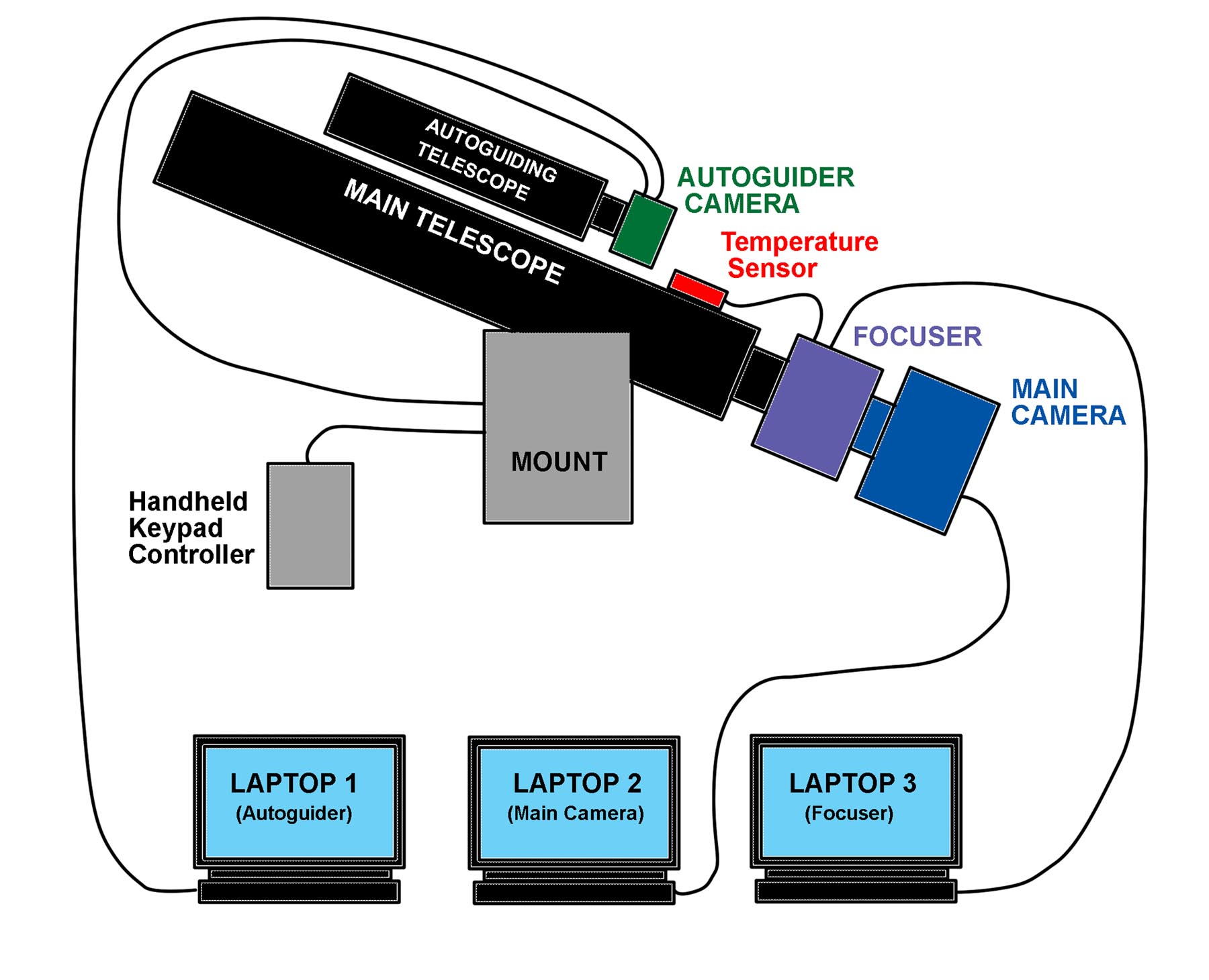
Figure 15. Diagrammatic representation of the control system for the SOCO imaging system.
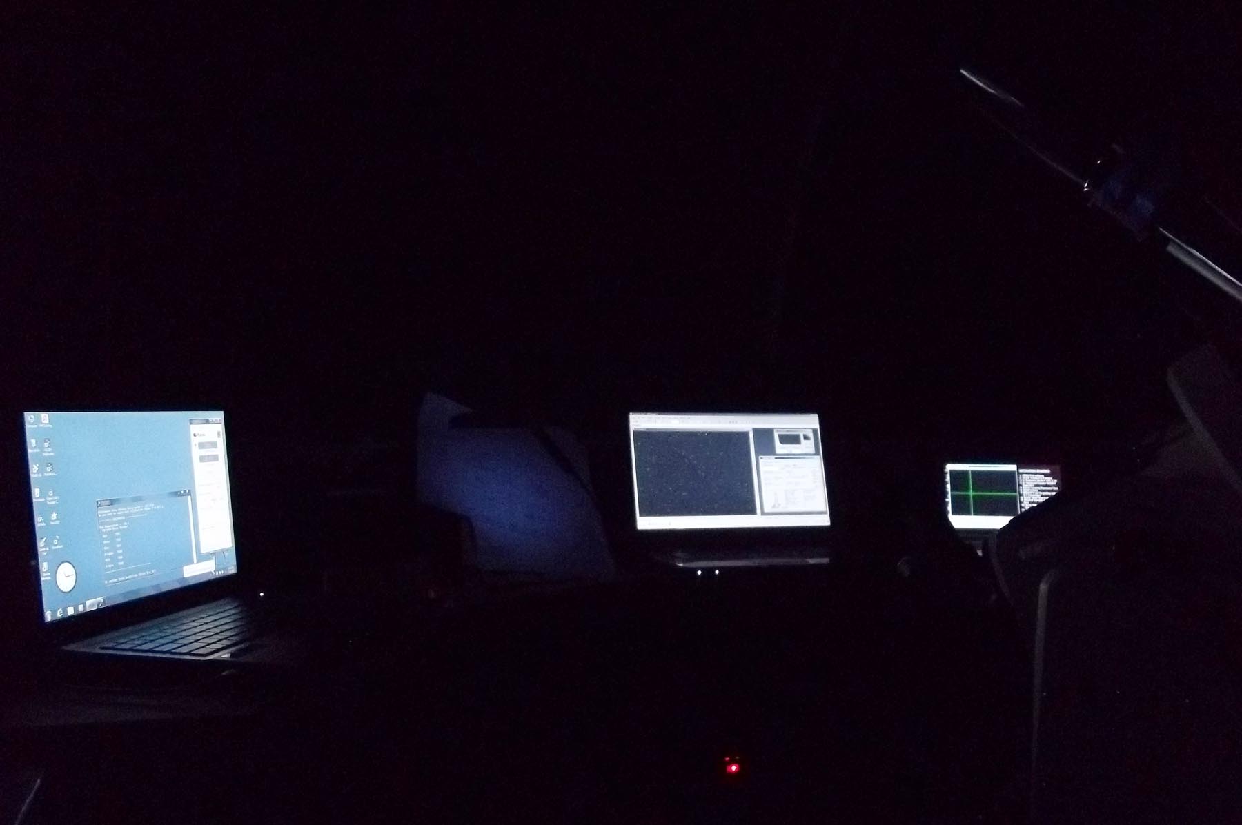
Figure 16. View inside SOCO when the imaging system is running. Focusing laptop is on the left, main camera laptop in the center, and autoguiding laptop on the right.
Auxilliary Optics
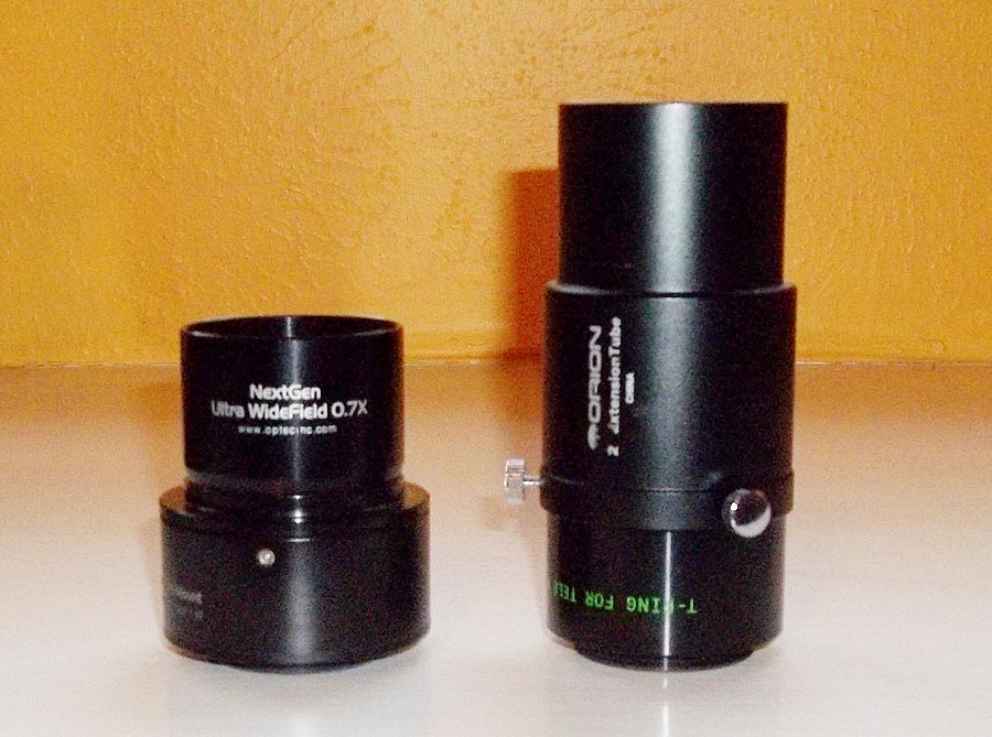
Figure 17. The Optec NextGen Ultra Widefield 0.7X focal reducer (left) and the TeleVue 2X PowerMate focal extender(right).
Table 1. Comparison of characteristics for the three SOCO optical systems.
|
As indicated in Table 1, use of the Optec focal reducer allows larger objects to be fit in the FOV. However, it's still not enough the contain really big astronomical objects like the Andromeda Galaxy (M 31), which must be captured using mosaics. Also, there is noticeable vignetting in the corners of the images prodiced using the Optec focal reducer (that must be corrected using flat frames), along with some distortion of stellar images. Still, use of the Optec focal reducer with the QSI camera is very effective in capturing those larger astronomical objects.
Use of the PowerMate 2X focal extender allows smaller objects (particularly galaxies) to occupy more of the image. However, while the images of the objects contain more detail, they do not appear quite as sharp as images made with the QSI camera alone. This is probably the result of magnifying the effects of atmospheric turbulence, i.e., scintillation effects are spread over more pixels. Also, use of the PowerMate requires longer exposure times, since you're reducing the photon flux density on the CCD chip. Note that, since the PowerMate increases the focal length of the tetelescope, additional back focus must be added between the scope and the camera. This is achieved by adding a 2" extension tube (sold by Orion, but similar items are available from many sources) to the front of the PowerMate (see Figure 17).
One miscellaneous piece of equipment that has come in handy is shown in Figure 18. This is an Alnitak "Flat-Man" flat fielding electroluminescent panel used for shooting flat frames. With this device, I don't have to wait until dawn or dusk to shoot sky flats. The electroluminescent panel produces a uniform illumination across its surface, and its brightness is continuously adjustable using the softweare that comes with it. These panels are available in a variety of shapes and sizes. I chose one that was slightly larger than the aperture of the SOCO telescope. Using some appropriately sized PVC pipe and a piece of wood, I built a holder for the Flat-Man that allows it to be slipped over the end of the telescope. Kind of a thrown-together thing but works great!
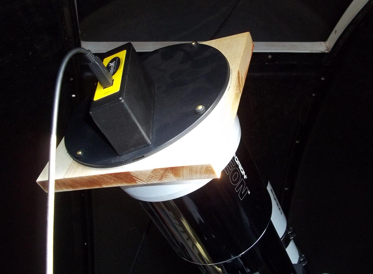
| Figure 18. The Alnitak "Flat-Man" flat fielding electroluminescent panel with custom-built holder. |
Update: The development of procedures for modeling flat images has made the current use of this device unnecessary.
While I have been pleased with what I have been able to do with the current suite of astronomical equipment at SOCO, there is always room for improvement. As previously stated, recent acquisitions of selected pieces of equipment (telescope mount, focuser, camera upgrade) have been made with the future in mind. In particular, the acquisition of a larger telescope will be a priority within the next couple of years. Since SOCO is a private observatory, there are limitations to what might realistically be acquired. Along with the typical kinds of research one can do on this topic, I have also been able to see several telescopes in person that are in the range of potential candidates.
One scope that I am familiar with is the main telescope at the nearby Texas Tech University Observatory. This is a 20-inch PlaneWave Instruments CDK-20 (Figure 19). This is the "target type" of telescope that I hope to acquire for SOCO. The Astro-Physics 1600GTO mount and Optec TCF-S3i focuser are compatible for use with this scope, so the only purchase would be the scope optical tube assembly (OTA).
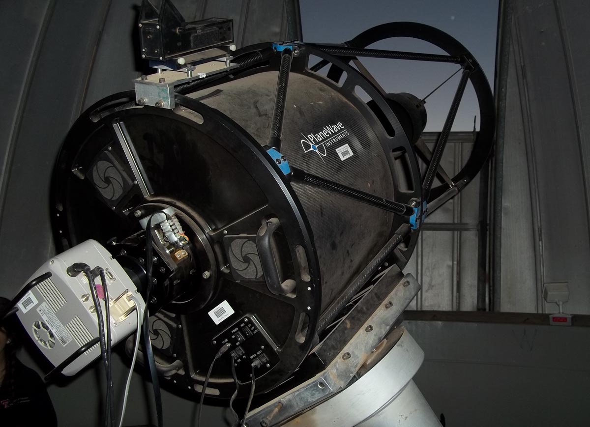
| Figure 19. The (rather dusty) PlaneWave CDK-20 telescope at the Texas Tech University Observatory. |
Acquiring a new telescope like the CDK-20 wouls also require building a larger observatory. The current 8-foot diameter dome of SOCO would not adequately hold a scope the size of the CDK-20. Luckily, PolyDome (the manufacturer of the current SOCO building) offers the ExploraDome II, an observatory building with an 11-foot dome. This would be adequate for a scope the size of the CDK-20.
So, there's much to be satisfied with at SOCO, and there's much to look forward to.
Questions or comments? Email SOCO@cat-star.org
 Return to SOCO Main Page