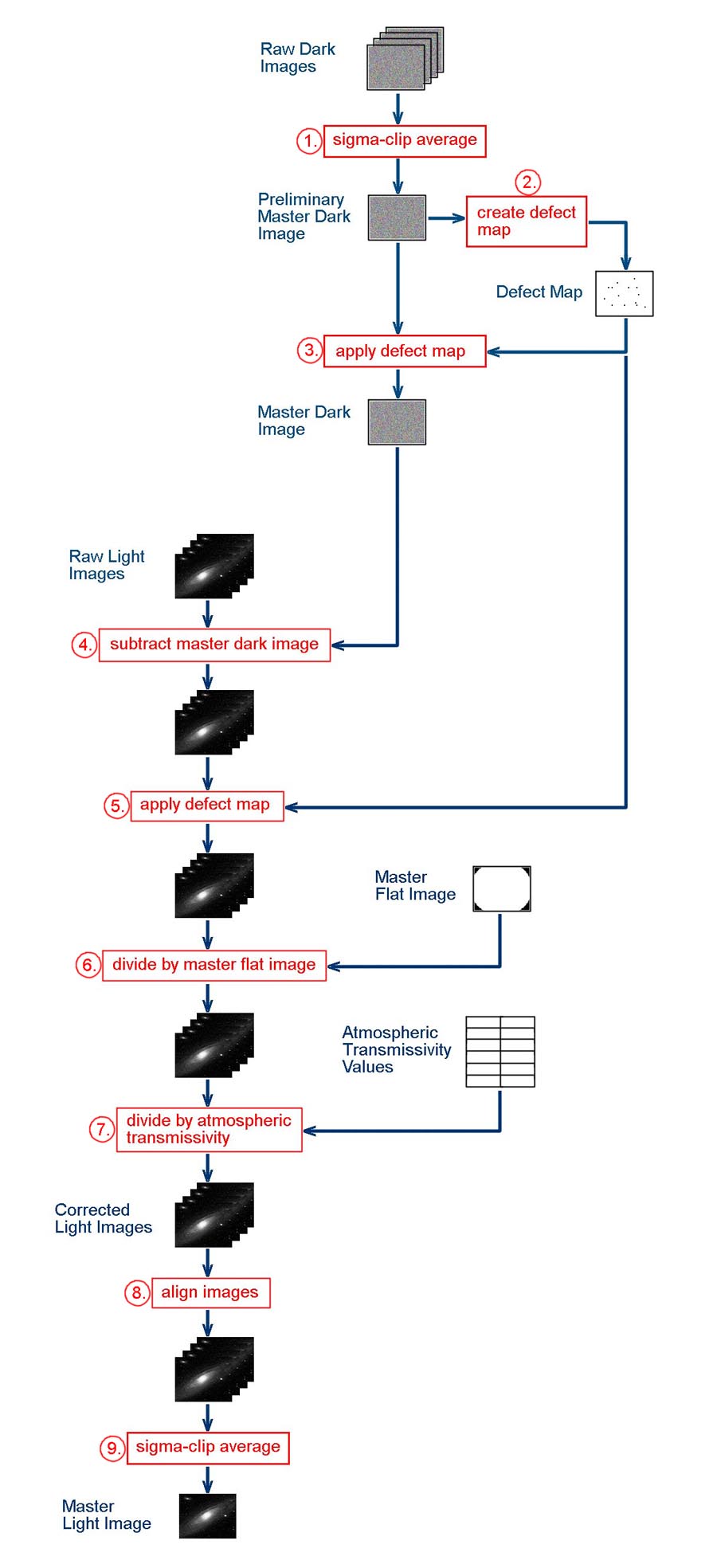
Figure 1. Flowchart of image processing activities for creating a master light image for a given spectral band.
Basic FITS Image Processing, Part I: Creating Master Light Images The standard procedure in modern astro-imaging is to acquire a number of individual FITS images of the astronomical target in a given monochrome waveband (such as Red, Green, Blue, Hα, Hβ, or OIII). These individual images are then processed to produce a single "master" image for that spectral band (called a "Master Light Image") with an increased signal-to-noise ratio, correction for atmospheric transmission effects, and removal of artifacts related to the operating characteristics of the imaging system. Master light images produced in this manner can later be combined through additional processing to produce a composite color image of the target. In Part I, I will describe the procedure that I have worked out to produce master light images. Here, "light images" refer to those that contain image data for the astronomical target, This procedure can be applied to the set of images acquired for any spectral band (Red, Green, Blue, Luminance, Hα, Hβ, OIII, SII, etc.). The result is a master light image for that spectral band. The steps in the procedure are outlined in the flowchart presented in Figure 1. In the flowchart, individual image processing activities are numbered and highlighted in red. Starting, intermediate, and final products are identified using blue text. In general, the steps in the processing procedure should be performed in the order indicated in Figure 1. Depending upon the image processing software used, it may be possible to automate some sequences of steps. In doing so, however, you should be sure that the software is actually performing the processing activities in the correct manner— some processing functions in software packages may have hidden steps or assumptions that may cause the imagery to be processed in an unexpected manner (the problem of "black box" processing). When in doubt, it's best to process things manually using the basic image processing functions (subtracting, dividing, averaging, etc.) in the software package. I provide detailed instructions for performing the processing using AIP4WinV2. Other software packages can most likely perform similar functions, and the processing procedure can be adapted accordingly.
(April 2015)
Figure 1. Flowchart of image processing activities for creating a master light image for a given spectral band.
The basic things you start out with are a set of raw light images and a set of raw dark images, where the dark images have been acquired for the same exposure time and at the same camera temperature as the light images. The dark images are necessary not only for creating the Master Dark Image (for removing thermal noise from the light imagery) but also for creating the Defect Map (for fixing hot pixels in the imagery). If you already have an appropriate Master Dark Image and Defect Map, you can skip the first three steps in the procedure. Otherwise, the sequence of steps in the image processing procedure is as follows.
1. Sigma-clip average raw dark images. The raw dark images contain hot pixels and cosmic ray hits. The use of sigma-clip averaging of the dark images rather than regular averaging is effective in removing the cosmic ray hits. The resulting Preliminary Master Dark Image will not contain cosmic ray hits, but will still contain hot pixels. Hot pixels will be removed in a later step. In AIP4WinV2, the sequence of actions for sigma-clip averaging the raw dark images is as follows.
Go to: Multi-Image > Auto-Process > Deep Sky…
In the AutoProcess Multiple Images box, select all the raw dark image files. From the Process Type drop-down, select Sigma-Clip Avg Stack.
Click “OK”. One dark image will be displayed. A box saying “For Sigma-Clip processing, a sky background sample must first be selected” will pop up. Click “OK” in that box.
In the displayed image, place the cursor in a uniform area and left-click. Then click the “Bkgnd” button in the AutoProcess Multiple Images box. A yellow box will appear at that location in the image.
Click “OK”. After processing, a sigma-clipped average dark image will be displayed. Save this image as the (preliminary) master dark image.
Close the AutoProcess Multiple Images box and any opened images.
2. Create the Defect Map. The Preliminary Master Dark Image will be used to create the Defect Map. Since cosmic ray hits have already been removed from the dark image, the only bright "defects" will be hot pixels. Thus, the Defect Map can be used to remove the hot pixels from the Master Dark Image and (later) from the light images. In AIP4WinV2, the sequence of actions listed below will allow the creation of the Defect Map.
Open the preliminary master dark image.
Create an inverse of the master dark:
Enhance > Pixel Ops > Invert
In the Image Display Control box, manually decrease the white setting until the distribution of black pixels in the image stays the same. This is done by clicking the second button from the right under the “User Black/White” section of that box. Note the numerical value in the box above this button—this is the current white value.
Create a thresholded version of the inverted image:
Enhance > Pixel Ops > Threshold…
A small “Threshold” box will appear. Type in a value for “Pixel Value” equal to the current white value noted earlier. Click “Apply”.
A thresholded image will be displayed in which the black pixels represent hot pixels. This step can be repeated if necessary with slightly different thresholding values until you’re satisfied that the resulting image is a good representation of the hot pixels.
Classify the defects (black pixels) in this image:
Calibrate > Defect Correction > Classify Defects
Copy the classified image to a defect map:
Calibrate > Defect Correction > Copy Image to Defect Map
Save the defect map:
Calibrate > Defect Correction > Save Defect Map
Close all displayed files.
3. Apply the Defect Map to the Preliminary Master Dark Image. To remove the hot pixels from the Preliminary Master Dark Image, apply the Defect Map to it. In AIP4WinV2, the sequence of actions listed below will accomplish this. The result will be the Master Dark Image, which will not contain cosmic ray hits or hot pixels.
To insure that the proper defect map is loaded in the software, first clear the defect map buffer:
Calibrate > Master Frames > Clear > Defect Map
Then load the previously created defect map:
Calibrate > Defect Correction > Load Defect Map
This defect map will remain the defect map buffer for the remainder of the image processing session. It is not necessary to manually open the Defect Map.
To apply the Defect Map:
Open the master dark image.
Calibrate > Manual Calibration > Apply Defect Map to Image
Save the resulting image as the new Master Dark Image.
You now have the Master Dark Image and the Defect Map. They will be used in the following steps in processing the raw light images. The next three steps involve correcting the raw light imagery for artifacts (thermal noise, hot pixels, dust "doughnuts" and vignetting) related to the operation of the imaging system.
4. Subtract the Master Dark Image from each raw light image. Depending on the exposure time and temperature of the imaging sensor, there will be a certain amount of thermal noise mixed in with the image signal in the raw light images. In this step, the thermal noise will be removed by subtracting the Master Dark Image from each raw light image. In AIP4WinV2, the sequence of actions listed below will accomplish this.
To subtract the Master Dark Image from each raw light image:
Open the Master Dark Image and all the raw light images.
Subtract the Master Dark Image from each of the raw light images:
Multi-Image > Image Math…
An Image Math box will appear. Select a raw light image for A and the Master Dark Image for B. Select “Minus A-B” for the math operation. Click the “Perform Math Operation” button.
Save (over-write) the resulting corrected light image.
Repeat this operation for all the opened raw light images.
Close all opened files.
5. Apply the Defect Map to each raw light image. In this step, applying the previously created Defect Map will remove the hot pixels from the raw light images. This assumes that the previously created Defect Map is still in the defect map buffer of the image processing software. If it's not, re-load it into the buffer (see Step 3). Note that applying the Defect Map must be done before the light images are aligned. This is because the positions of the hot pixels in the light image are fixed relative to the image frame. When a light image is aligned, the positions of the hot pixels will move in the image along with the other aligned features (stars, etc.). Thus, they will no longer line up with the corresponding features in the Defect Map, and applying the Defect Map won't correct them. After this step, the light images will not contain hot pixels but will still contain cosmic ray hits. These will be fixed in a later step. In AIP4WinV2, the sequence of actions listed below will apply the Defect Map to each raw light image.
To apply the defect map to each raw light image:
Open all the raw light images.
Sequentially apply the defect map to each opened light image:
Calibrate > Manual Calibration > Apply Defect Map to Image
Save each corrected light image (over-write the previous version).
6. Divide each raw light image by the Master Flat Image. This process assumes that you have already created Master Flat Images for the various spectral bands of imagery that you acquire. In this step, applying the previously created Master Flat Image will correct the raw light images by flattening out illumination artifacts cause by vignetting in the optical system, and will remove the annoying dust "doughnut" features in the imagery caused by dust particles on optical surfaces in the imaging system. As with applying the Defect Map in the previous step, applying the Master Flat Image must be done before the light images are aligned. Again, this is because the positions of the illumination artifacts in the light image are fixed relative to the image frame. When a light image is aligned, the positions of the artifacts will move in the image along with the other aligned features. Thus, they will no longer line up correctly with the corresponding features in the Master Flat Image. In this case, applying the Master Flat Image won't completely correct them and may introduce additional artifacts into the imagery. In AIP4WinV2, the sequence of actions listed below will apply the Master Flat Image to each raw light image.
Open the Master Flat Image and all the raw light images.
Divide each raw light image by the Master Flat Image:
Multi-Image > Image Math…
An Image Math box will appear. Select a raw light image for A and the Master Flat Image for B. Select “Divide A/B” for the math operation. Click the “Perform Math Operation” button.
Save (over-write) the resulting flatted light image.
Repeat this operation for all the opened light images.
Close all opened files.
At this point, we have corrected the raw light imagery for artifacts (thermal noise, hot pixels, dust "doughnuts" and vignetting) related to the operation of the imaging system. So, now we have "pure" image data in the light images (except that they still contain cosmic ray hits). Following steps will calibrate these image data for external features caused by atmospheric transmissivity and will fix the cosmic ray hits.
7. Divide each raw light image by the corresponding Atmospheric Transmissivity. Individual imaging sessions may last several hours, and the total time needed to image an object may require imaging sessions on several nights. As a result, the elevation of the target above the horizon will likely be different for each of the acquired raw light images. Thus, the optical air mass X (a function of the elevation angle) will be different for each raw light image. The light imagery must be calibrated for this. Otherwise, the color balance within each light image will be different, which could throw off the overall color balance of the final composite color image formed from the light images. Calibration is usually achieved by dividing each raw light image by the corresponding value of atmospheric transmissivity (A), thus correcting each light image to the situation as if the object were directly overhead (i.e., X = 1) when it was imaged. Note that calibrating for atmospheric transmissivity must be done before the raw light images are stacked (averaged). Stacking the light images simply averages the effects of atmospheric transmissivity— this is not the same as calibrating for it.
The value of A for a given raw light image can be calculated using the following equation:
A = 10 -0.4 k [sec(SZA) - 1]
where k is the value of the atmospheric extinction coefficient for the spectral waveband of the light imagery and SZA is the stellar zenith angle (the complement of the elevation angle) of the object. There are a number of ways to get the elevation angle of the object. I provide a computer application for calculating stellar elevation angle. Alternately, you can go go into a planetarium software application (like Cartes du Ciel or Starry Night) and pick off the elevation angles for the object at the appropriate image acquisition times (image aquisition time is included in the FITS file header). The result of this exercise is a table of A values for the set of raw light images.
Having determined the atmospheric transmissivity values, we can divide each light image by its corresponding A value. In image processing software packages, this can be done using the "Pixel Math" function present in most of them. In AIP4WinV2, this can be accomplished as follows.
Open a raw light image (I find it's easier to process each light image separately).
Open the "Pixel Math" tool:
Enhance > Pixel Math...
In the Pixel Math box, type in the appropriate value for A in the space provided.
Among the button representing Math Functions, click the one labelled "pv/A".
Save (over-write) the resulting calibrated light image.
Repeat this operation for all the raw light images.
Close all opened files.
8. Align the light images. All processing functions on the individual raw light images are complete. Now, the corrected light images need to be aligned in preparation for stacking (averaging). In AIP4WinV2, the sequence of actions listed below can be used to align the corrected light images.
In the set of light images to be registered, identify one that will serve as the “master image” to which all the other images will be aligned.
Open this master image:
File > Open Image…
Open the first light image to be aligned with the master image. Note: Multiple light images can be opened for alignment.
Start the alignment (registration) procedure:
Multi-Image > Register Images…
In the Register Images box, select the master light image in the Master Image box from the dropdown menu.
Click the "Select Slave Images" button.
In the Select Slave Images for Registration box, highlight the image to be aligned, and click the "Add>>" button. Then click the "OK" button.
In the Register Images box, click the "Register Images" button.
In the Register Images box, set the Track Radius to 20 using the slider.
Go to the displayed master image (it should be on top). Using the sliders along the bottom and side of the image, shift the display of the image to show the lower left corner of the image. Pick out an isolated star of medium magnitude. Place the point of the cursor on the center of this star and left-click the mouse. A white circle should appear around the star. In the Register Images box, click the "Star 1" button. The circle should turn green and the number 1 will be next to it.
Go back to the displayed master image. Using the sliders along the bottom and side of the image, shift the display of the image to show the upper right corner of the image. Pick out an isolated star of medium magnitude. Place the point of the cursor on the center of this star and left-click the mouse. A white circle should appear around the star. In the Register Images box, click the "Star 2" button. The circle should turn green and the number 2 will be next to it. In the Register Images box, click the "OK" button. The light image to be aligned will now appear on top. Using the sliders along the bottom and side of the image, shift the display of the image to show the lower left corner of the image. Verify that the previously selected star is within the yellow circle with the number 1 next to it. Then, using the sliders along the bottom and side of the image, shift the display of the image to show the upper right corner of the image. Verify that the previously selected star is within the yellow circle with the number 2 next to it.
If both stars are within their respective yellow circles, click the "OK" button in the Register Images box (this is the second time you’ve clicked it). An aligned version of the slave image will be displayed.
Save the resulting aligned image in place of the opened one (choose "Yes" when it asks if you want to overwrite existing file). Close the saved image.
Perform this operation for each of the light images that need alignment.
I find that the alignment procedure in AIP4WinV2 is a bit tedious. Since I also have Maxim DL, I normally use the alignment procedure in it. The sequence of actions for aligning images in Maxim DL is as follows.
Drag and drop light image files to be aligned onto the Maxim DL workspace. The last one will be displayed.
Align the images:
Process > Align...
"Select Images" box will appear. Click "Add All" button, then click "OK" button.
"Align Images" box will appear. In Align Mode, select "Auto-star matching" from the drop-down list.
Click "OK" — Alignment process will begin.
When finished, save aligned images. This can be done by clicking on the close button for each image and clicking "Yes" when asked to save changes to the file. This will occur for all files except the image used as the master file.
9. Sigma-clip average the light images. We're now ready to stack (average) the aligned, corrected light images to create the Master Light Image. You could use normal averaging here, but using sigma-clip averaging will finally remove the cosmic ray hits. In AIP4WinV2, the sequence of actions listed below can be used to stack the light images.
Create a Master Light Image using sigma-clip averaging:
Multi-Image > Auto-Process > Deep Sky…
In the AutoProcess Multiple Images box, select all the light image files. From the Process Type drop-down, select Sigma-Clip Avg Stack.
Click “OK”. One light image will be displayed. A box saying “For Sigma-Clip processing, a sky background sample must first be selected” will pop up. Click “OK” in that box.
In the displayed image, place the cursor in a uniform area (without stars) and left-click. Then click the “Bkgnd” button in the AutoProcess Multiple Images box. A yellow box will appear at that location in the image.
If there are some stars in the yellow box, repeat the previous function until you get a yellow box with no stars in it.
Click “OK”. After processing, a sigma-clipped average image will be displayed. Save this image as the Master Light Image.
The processing procedure is now complete. As I said earler, this procedure can be applied to the set of raw light images acquired for any spectral band (Red, Green, Blue, Luminance, Hα, Hβ, OIII, SII, etc.), with the result being a Master Light Image for that spectral band. In Part II of Basic FITS Processing, I describe an optional procedure for combining narrow-band (Hα, Hβ, OIII) Master Light Images with broad-band (Red, Green, Blue) Master Light Images to create a set of "hybrid" Red, Green and Blue Master Light Images. In Part III of Basic FITS Processing, I describe how regular or "hybrid" Master Light Images in the Red, Green and Blue spectral bands can be combined to create a composite "true" color image. The procedure described above provides basic processing of imagery acquired under practically all conditions. However, under certain circumstances, a revised version of the processing procudure can be used that will reduce the processing effort, particularly if you are manually processing all steps. In this shortcut approach, you still go through all the processing steps as in the original procedure, but the order is changed to allow stacking (averaging) the raw light images earlier in the process. To be able to use the shortcut processing method, the following conditions must apply: 1.) The set of raw light images must have been acquired with the target at a high evelation angle (SEA) above the horizon. Generally, SEA should be greater than around 60 degrees. This is because, at high elevation angles, the atmospheric transmissivity is near 1 and does not change much in that range of elevation angles. 2.) The set of raw light images must have been acquired over a relatively short time period. The time period should be short enough so that the SEA of the target does not change more than a couple of degrees. Along with the high elevation angle, this will allow you to apply a single average atmospheric transmissivity value. 3.) The image alignment needed for the set of images should be minimal. That is, the target object should not markedly change position within the image frame within the set of acquired images. Assuming that your telescope mount tracking is good over the (short) imaging period, this will usually be the case. There should be no pier flips during the period of image acquisition. Assuming these conditions are satisfied, then the Shortcut Method can be used and should produce similar results to those produced by the original procedure. The steps in the Shortcut Method are outlined in the flowchart presented in Figure 2.
Optional Shortcut Method
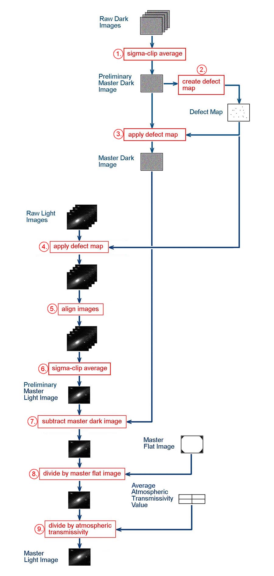
Figure 2. Flowchart of image processing activities in the Shortcut Method for creating a master light image for a given spectral band.
The sequence of steps in the shortcut processing procedure is as follows.
1. Sigma-clip average raw dark images. This is the same as in the original procedure. 2. Create the Defect Map. This is the same as in the original procedure. 3. Apply the Defect Map to the Preliminary Master Dark Image. This is the same as in the original procedure. 4. Apply the Defect Map to each raw light image. As in Step 5 of the original procedure, applying the previously created Defect Map will remove the hot pixels from the raw light images. This assumes that the previously created Defect Map is still in the defect map buffer of the image processing software. If it's not, re-load it into the buffer (see Step 3). As in the original procedure, applying the Defect Map must be done before the light images are aligned. In AIP4WinV2, use the the sequence of actions described in Step 5 in the original procedure to apply the Defect Map to each raw light image. 5. Align the light images. Here is where the Shortcut Method deviates from the original procedure. We will align the raw light images now so that they can be stacked (averaged) in the next step. In AIP4WinV2 or Maxim DL, use the same sequences of actions listed under Step 8 in the original procedure to align the raw light images. 6. Sigma-clip average the light images. We're now going to stack (average) the aligned raw light images to create a Preliminary Master Light Image. Again, you could use normal averaging here, but using sigma-clip averaging will remove the cosmic ray hits. In AIP4WinV2, the sequence of actions listed in Step 9 of the original procedure can be used to stack the light images. At this point, we have a Preliminary Master Light Image that has been corrected for hot pixels and cosmic ray hits. From now on in the procedure, we will work on this single image and correct it for the other factors (thermal noise, dust "doughnuts" and vignetting) that were addressed in the original procedure. 7. Subtract the Master Dark Image from the Preliminary Master Light Image. This is the same action as in Step 4 of the original procedure, but you will now be performing it on only one image (the Preliminary Master Light Image). In AIP4WinV2, the sequence of actions listed below will accomplish this.
To subtract the Master Dark Image from the Preliminary Master Light Image:
Open the Master Dark Image and the Preliminary Master Light Image.
Subtract the Master Dark Image from the Preliminary Master Light Image:
Multi-Image > Image Math…
An Image Math box will appear. Select the Preliminary Master Light Image for A and the Master Dark Image for B. Select “Minus A-B” for the math operation. Click the “Perform Math Operation” button.
Save (over-write) the resulting corrected image.
Close all opened files.
8. Divide the Preliminary Master Light Image by the Master Flat Image. As before, this process assumes that you have already created Master Flat Images for the various spectral bands of imagery that you acquire. In this step, applying the previously created Master Flat Image will correct the the Preliminary Master Light Image by flattening out illumination artifacts cause by vignetting in the optical system, and will remove the annoying dust "doughnut" features in the image caused by dust particles on optical surfaces in the imaging system. In AIP4WinV2, the sequence of actions listed below will apply the Master Flat Image to the Preliminary Master Light Image.
Open the Master Flat Image and the Preliminary Master Light Image.
Divide the Preliminary Master Light Image by the Master Flat Image:
Multi-Image > Image Math…
An Image Math box will appear. Select the Preliminary Master Light Image for A and the Master Flat Image for B. Select “Divide A/B” for the math operation. Click the “Perform Math Operation” button.
Save (over-write) the resulting flatted image.
Close all opened files.
9. Divide the Preliminary Master Light Image by the Average Atmospheric Transmissivity. We will still need to calculate the values of the atmospheric transmissivity (A) for each of the original raw light images, as in the original procedure. The same procedure described in Step 7 of the original procedure can be used to do this. Once these values have been calculated, we will take the average of them. This average atmospheric transmissivity value will then be applied to the Preliminary Master Light Image using the "Pixel Math" function. In AIP4WinV2, this can be accomplished as follows.
Open the Preliminary Master Light Image.
Open the "Pixel Math" tool:
Enhance > Pixel Math...
In the Pixel Math box, type in the average value for A in the space provided.
Among the button representing Math Functions, click the one labelled "pv/A".
Save (over-write) the resulting calibrated image.
Close all opened files.
The Shortcut processing procedure is now complete. The resulting Master Light Image should be similar to that produced by the original processing procedure if the previously described conditions were satisfied.
 Return to SOCO Image Processing Page
Return to SOCO Main Page
Return to SOCO Image Processing Page
Return to SOCO Main Page
Questions or comments? Email SOCO@cat-star.org