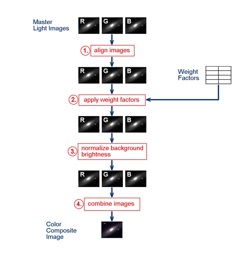
Figure 1. Flowchart of image processing activities for creating a composite "true" color image.
Basic FITS Image Processing, Part III: Combining Red, Green and Blue Master Light Images to create "True" Color Images The basic procedure for creating color composite images of astronomical objects is to combine individual light images acquired in the Red, Green and Blue wavebands, where the Red image is placed in the R channel of the color image, the Green image is placed in the G channel of the color image, and the Blue image is placed in the B channel of the color image. In Part I, I described how Master Light Images in the various spectral bands (Red, Green, Blue, Luminance, Hα, Hβ, OIII, SII, etc.) can be produced from sets of raw light images. In Part II, I described how narrow-band (Hα, Hβ, OIII) Master Light Images can be combined with broad-band (Red, Green, Blue) Master Light Images to create a set of "hybrid" Red, Green and Blue Master Light Images. In Part III, I will describe a procedure for combining either regular Master Light Images in the Red, Green and Blue wavebands, or "hybrid" Master Light Images in the Red, Green and Blue wavebands, to create a composite color image. This procedure is designed to produce "true" color images, i.e., what astronomical objects would look like if our color vision were sensitive enough to adequately respond to the low levels of light that we receive from them. The procedure for creating a composite color image from Red, Green and Blue Master Light Images is fairly straight-forward. The procedure is the same whether regular or "hybrid" Master Light Images in the Red, Green and Blue wavebands are used. The steps in the procedure are outlined in the flowchart presented in Figure 1. In the flowchart, individual image processing activities are numbered and highlighted in red. Starting, intermediate, and final products are identified using blue text. In general, the steps in the processing procedure should be performed in the order indicated in Figure 1. Depending upon the image processing software used, it may be possible to automate some sequences of steps. In doing so, however, you should be sure that the software is actually performing the processing activities in the correct manner— some processing functions in software packages may have hidden steps or assumptions that may cause the imagery to be processed in an unexpected manner (the problem of "black box" processing). When in doubt, it's best to process things manually using the basic image processing functions (subtracting, dividing, averaging, etc.) in the software package. I provide detailed instructions for performing the processing using AIP4WinV2. Other software packages can most likely perform similar functions, and the processing procedure can be adapted accordingly.
(April 2015)
Figure 1. Flowchart of image processing activities for creating a composite "true" color image.
To start the processing procedure, we need a set of Red (R), Green (G), and Blue (B) Master Light Images created using the procedures described in Part I or Part II. Use of Master Light Images derived from other processing procedures might not produce acceptable results, unless these other processing procedures contain the same steps as used in my procedure. The sequence of steps in the image processing procedure outlined in Figure 1 is as follows.
1. Align the Master Light Images. In Part I, the raw ligfht images were aligned to produce a Master Light Image for a given spectral band. However, the resulting Red, Green and Blue Master Light Images also need to be aligned, since there could be differences in overall alignment between the spectral band image sets. In AIP4WinV2, the sequence of actions listed below can be used to align the Master Light Images (this is the same procedure used in Part I).
In the set of Red, Green and Blue Master Light Images, identify one that will serve as the ōmaster imageö to which the other two images will be aligned.
Open this master image:
File > Open Imageģ
Open the the remaining two Master Light Images to be aligned.
Start the alignment (registration) procedure:
Multi-Image > Register Imagesģ
In the Register Images box, select the master image in the Master Image box from the dropdown menu.
Click the "Select Slave Images" button.
In the Select Slave Images for Registration box, highlight one of the other images to be aligned, and click the "Add>>" button. Then click the "OK" button.
In the Register Images box, click the "Register Images" button.
In the Register Images box, set the Track Radius to 20 using the slider.
Go to the displayed master image (it should be on top). Using the sliders along the bottom and side of the image, shift the display of the image to show the lower left corner of the image. Pick out an isolated star of medium magnitude. Place the point of the cursor on the center of this star and left-click the mouse. A white circle should appear around the star. In the Register Images box, click the "Star 1" button. The circle should turn green and the number 1 will be next to it.
Go back to the displayed master image. Using the sliders along the bottom and side of the image, shift the display of the image to show the upper right corner of the image. Pick out an isolated star of medium magnitude. Place the point of the cursor on the center of this star and left-click the mouse. A white circle should appear around the star. In the Register Images box, click the "Star 2" button. The circle should turn green and the number 2 will be next to it. In the Register Images box, click the "OK" button. The light image to be aligned will now appear on top. Using the sliders along the bottom and side of the image, shift the display of the image to show the lower left corner of the image. Verify that the previously selected star is within the yellow circle with the number 1 next to it. Then, using the sliders along the bottom and side of the image, shift the display of the image to show the upper right corner of the image. Verify that the previously selected star is within the yellow circle with the number 2 next to it.
If both stars are within their respective yellow circles, click the "OK" button in the Register Images box (this is the second time youÆve clicked it). An aligned version of the slave image will be displayed.
Save the resulting aligned image in place of the opened one (choose "Yes" when it asks if you want to overwrite existing file). Close the saved image.
Repeat this operation for the other Master Light Image to be aligned.
The alignment procedure in AIP4WinV2 is a bit tedious. Since I also have Maxim DL, I normally use the alignment procedure in it. The sequence of actions for aligning images in Maxim DL is as follows.
Drag and drop the Red, Green and Blue Master Light Image files to be aligned onto the Maxim DL workspace. The last one will be displayed.
Align the images:
Process > Align...
"Select Images" box will appear. Click "Add All" button, then click "OK" button.
"Align Images" box will appear. In Align Mode, select "Auto-star matching" from the drop-down list.
Click "OK" — Alignment process will begin.
When finished, save aligned images. This can be done by clicking on the close button for each image and clicking "Yes" when asked to save changes to the file. This will occur for all files except the image used as the master file.
2. Divide each Master Light Image by the corresponding Weight Factor. The Red, Green and Blue Master Light Images must be divided by weight factors (W) to insure the proper color balance in the resulting composite color image. There will be a different value for the weight factor for each of the Master Light Images. In image processing software packages, dividing an image by a specific value can be done using the "Pixel Math" function present in most of them. In AIP4WinV2, this can be accomplished as follows.
Open one of the Master Light Images (I find it's easier to process each image separately).
Open the "Pixel Math" tool:
Enhance > Pixel Math...
In the Pixel Math box, type in the appropriate value for W in the space provided.
Among the button representing Math Functions, click the one labelled "pv/A".
Save (over-write) the resulting weighted Master Light Image.
Repeat this operation for the two other Master Light Images.
Close all opened files.
3. Normalize the background sky brightness (skylight). The skylight brightness of the background in the Master Light Images can affect the resulting color balance in the composite color image. The background brightness among the three Master Light Images should be normalized to remove any color imbalance in the final composite color image due to skylight. I describe the procedure for determining and normalizing background brightness in a separate webpage.
4. Combine the Master Light Images. This is the final step in the processing procedure. All corrections and calibrations have already been performed, so now we just have to turn the three monochrome Master Light Images into a Composite Color Image. All image processing software packages contain a tool to do this. In AIP4WinV2, this can be accomplished as follows.
Go to: Color > Join Colors > RGB -> Colorģ
In the Join RGB Channels -> Color box, select the proper Red, Green and Blue Master Light Images from the drop-down choices
Click the ōJoin RGB Channelsö box. After processing, a composite color image will be displayed. Save this image as the final Composite Color Image.
Close any opened images.
The processing procedure is now complete. The resulting Color Composite Image should represent a "true" color version of the astronomical object. For images that have a wide range of brightness, it may still be necessary to perform some type of contrast stretching on the color image to bring out the object's features or minimize saturation of parts of the image. In applying such post-processing operations, it is important that they be applied equally to all three color channels (R, G and B) in the Composite Color Image. Otherwise, the overall color balance in the Composite Color Image may be messed up.
 Return to SOCO Image Processing Page
Return to SOCO Main Page
Return to SOCO Image Processing Page
Return to SOCO Main Page
Questions or comments? Email SOCO@cat-star.org